Michael Danielsson | CEO, Vindus Fans | Published August 11, 2026
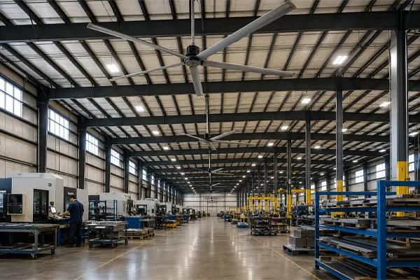
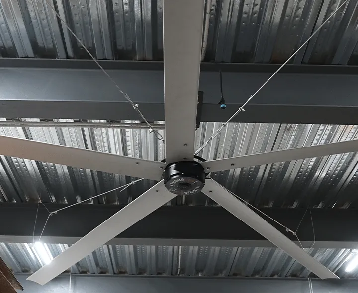
An HVLS fan system is the fan assembly plus everything that makes it work in a specific building: motor and drive, mounting structure and downrod, power and control cabling, the control interface, and commissioning. Treating it as a system rather than a purchased unit is what separates a layout that performs from one that gets switched off.
The Fan Is Roughly Half the Decision
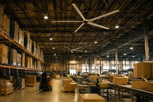
Buyers arrive with a diameter in mind and a budget line labelled “fans.” Then the electrical contractor asks where the disconnect goes, the structural engineer asks what the truss can carry, and the facility manager asks who climbs 30 feet to change a speed setting.
Six components make up the system, and only the first is on the spec sheet in most people’s hands:
- Fan assembly— hub, blades, motor. Diameter and motor architecture set airflow and noise behaviour.
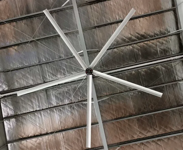
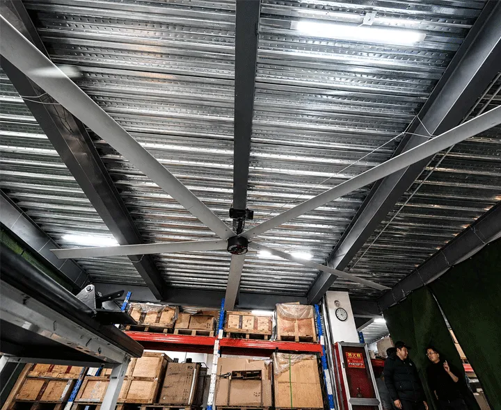
- Mounting interface— the bracket, the downrod, and the structural member it attaches to. This is where most retrofit cost surprises live.
- Drive and power feed— the variable-frequency drive, circuit, disconnect and conductor run.
- Control interface— where a human changes speed and direction, and whether that point is reachable without a lift.
- Building integration— whether the fan takes signals from a building automation system or runs standalone, and how it coordinates with heating and cooling.
- Commissioning and documentation— speed setting by zone, rotation direction verification, torque records, and lockout/tagout procedure.
Skip any of the last three and you have installed equipment rather than commissioned a system. The distinction shows up six months later, when nobody remembers what the summer settings were.
Cabling and Control Architecture
This is the least glamorous part of the specification and the one that generates the most change orders.
A conventional HVLS installation runs power to a remote drive enclosure, then separate control wiring to a wall-mounted interface, then a signal path back to the fan. Three runs, three termination points, three things to troubleshoot when a fan will not start. In a large building with long conductor distances, the labour on those runs is a real line item.
Vindus P780 and P730 units use a single ceiling-to-floor cable with a floor-level integrated HMI. The practical consequence is fewer terminations and a diagnostic point a technician can reach standing on the floor. For a facility running fans across multiple zones, that also means speed adjustment during the first hot week does not require scheduling a lift.
For multi-unit installations, decide early how many independent control groups the operation needs. A packing area and a bulk storage aisle rarely want the same speed, and grouping them together to save on control hardware tends to produce a compromise setting that suits neither. Independent grouping is almost always cheaper than adding a fan to compensate.
Structural Attachment Is an Engineering Question
A 24-foot fan is a rotating mass permanently suspended over an occupied floor. Three things need a signature from someone qualified, not a rule of thumb from a catalog.
Static and dynamic load at the attachment point. The fan’s weight is the easy number. Rotational imbalance, start-up torque and any building movement matter too, and a direct-drive assembly places less mass at that point than an equivalent gearbox-driven unit because there is no gear housing in the hub.
Downrod length and vibration. A longer downrod brings the fan into the working height band in very high buildings, but it also changes the assembly’s natural frequency. Above the specified ceiling range, this stops being selection and becomes engineering.
Access for inspection and lockout/tagout. If the fan cannot be safely reached and isolated, it will not be inspected, and an uninspected fan over a work area is a liability rather than an asset. Confirm the access plan before ordering, not after the lift is scheduled.
Direct Drive vs Gearbox-Driven Systems
| Dimension |
Direct drive (PMSM) |
Gearbox-driven |
| Drivetrain |
Motor coupled directly to the hub |
Motor plus reduction gearbox |
| Mechanical loss points |
Bearings only |
Bearings, gear mesh, seals |
| Scheduled oil service |
None |
Periodic inspection and oil change |
| Leak risk below the fan |
None |
Present; seals wear |
| Tonal noise source |
Aerodynamic only |
Aerodynamic plus gear mesh whine |
| Mass at the mounting point |
Inférieur |
Plus haut |
| Speed control |
Electronic via integrated drive |
Fixed ratio plus drive |
| Field service access needed |
Inspection only |
Inspection plus lubrication access |
I led development of direct-drive HVLS models at MacroAir before this work at Vindus, and from a systems perspective the last two rows carry more weight than the efficiency argument people usually lead with. Every scheduled service event above a production floor is a coordination problem: a lift, an aisle closed, a lockout procedure, and a maintenance window negotiated with operations. Removing oil service removes that recurring negotiation.
Range Specifications Across the Three Series
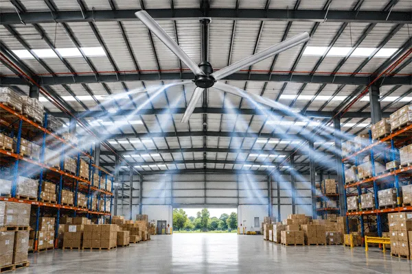
Series selection follows clear ceiling height first, then diameter.
| Specification |
P680 Series |
P730 Series |
P780 Series |
| Diamètres |
8–14 ft |
16 ft, 18 ft |
20 ft, 24 ft |
| Suitable ceiling height |
10–25 ft |
20–33 ft |
20–33 ft |
| Moteur |
PMSM, direct drive |
PMSM, direct drive |
PMSM, direct drive |
| Power at max speed |
Per configuration |
Under 1,000 W |
Under 1,000 W |
| Contrôle |
Floor-level HMI |
Floor-level integrated HMI |
Floor-level integrated HMI |
| Cabling |
Per configuration |
Single ceiling-to-floor cable |
Single ceiling-to-floor cable |
| Typical fit |
Workshops, logistics areas, retail, restaurants, outdoor patios |
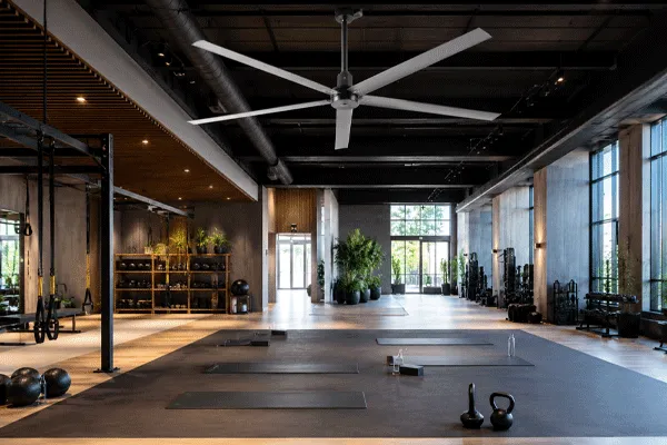
Gymnasiums, mid-span plants, field houses |
Large warehouses, high-bay manufacturing, arena-scale volumes |
| Performance basis |
AMCA 230-15, ANSI/ASHRAE 216P |
AMCA 230-15, ANSI/ASHRAE 216P |
AMCA 230-15, ANSI/ASHRAE 216P |
| Safety compliance |
CE, CB, EN, IEC |
CE, CB, EN, IEC |
CE, CB, EN, IEC |
| Garantie |
3 years on defective components |
3 years on defective components |
3 years on defective components |
Two entries in that table read as gaps and are deliberate. Power draw and cabling detail for the P680 Series vary by configuration and are not published as a single figure, so I am not going to state one. Rated CFM per model is not published for any series, and neither are prices — both follow from a layout review and a quote.
The standards row is a purchasing tool. AMCA 230-15 is the Air Movement and Control Association’s test method for air-circulating fan performance; ANSI/ASHRAE 216P defines how Ventilateur HVLS performance is characterized. When comparing systems, ask each vendor which method produced their airflow numbers. Compared with the category-typical practice of quoting airflow with no stated test basis, a standardized figure is the only one you can put next to another vendor’s and learn anything from.
Installation Sequence
- Survey clear height bay by bay.Measure to the lowest obstruction — sprinklers, lighting, ductwork, crane envelope, rack tops — not to the roof deck. The number often varies within one building.
- Produce the obstruction and occupancy overlay.Mark everything above roughly 10 feet, then mark where people and workstations actually are. Fan positions come from the intersection.
- Get structural sign-off on each attachment point.Include downrod length, bracket type and load figures. Resolve reinforcement needs here, where it is drawing work rather than field work.
- Coordinate the electrical path.Circuit, disconnect location, conductor route, and the control interface position. Confirm the floor-level HMI location is somewhere staff will actually use.
- Set the rigging and lockout/tagout plan.How the unit goes up, and how it will be isolated for every future inspection.
- Install, then verify rotation direction and torque all fasteners to specification.Record the values. This record is what a future technician needs.
- Commission by zone.Set summer and winter speeds per control group, walk the floor at peak occupancy, and adjust. Document the settings somewhere that survives staff turnover.
Edge Cases Worth Flagging Before Purchase Order
Ceiling heights above 33 feet. Outside the specified range for P780 and P730. Solvable with downrod engineering, but treat it as a design exercise with structural input.
Existing buildings with unknown truss capacity. Older facilities frequently lack usable structural drawings. Budget for investigation, and expect that reinforcement in a marginal structure can approach the equipment cost.
Retrofits into conditioned spaces with existing BAS. Integration scope needs defining early. Standalone operation is straightforward; coordinated control with heating setpoints is a controls project with its own line item.
Corrosive, dusty or wash-down environments. Motor and finish selection depend on the environment. Vindus publishes no per-model IP rating, so specify the environment in writing during the quote rather than assuming a standard configuration covers it.
Fixed acoustic limits. No per-model sound pressure figures are published, and I would rather say so than quote a number with no test standard or measurement distance attached. If a contractual dB limit applies, request measured data with those conditions stated.
What a Fan System Will Not Do
It does not ventilate. HVLS fans redistribute air already inside the building; outdoor air, CO₂ removal and fume exhaust remain the ventilation system’s job. A building failing an air-quality requirement will still fail it with fans running.
It does not dehumidify. Air movement improves evaporative cooling on skin, which is a comfort gain, not a moisture-load reduction.
It does not eliminate maintenance. A direct-drive system removes oil service, not inspection. Fasteners, blade condition, mounting hardware and electrical terminations still need a schedule.
And it is front-loaded on cost. The equipment plus structural and electrical work is a capital event, offset over seasons by a unit drawing under 1,000 W at full speed and by reduced heating demand in high-bay spaces. Facilities looking for an operating-expense-only solution will find the arithmetic works, but not in the first quarter.
FAQ
Q: What does an HVLS fan system include beyond the fan?
A: Mounting bracket and downrod, the structural attachment they connect to, the drive and power feed, the control interface, any building automation integration, and commissioning. The Vindus P780 and P730 consolidate power and control into a single ceiling-to-floor cable with a floor-level HMI, which reduces the termination and labour scope relative to separate power and control runs.
Q: Who needs to be involved in the installation?
A: A structural engineer for the attachment points, a licensed electrician for the circuit and disconnect, and a rigging plan for lifting the assembly. Facility operations should own the commissioning step, since they will be the ones adjusting settings.
Q: Can HVLS fans integrate with a building automation system?
A: Integration is supported, but scope it as its own task rather than an afterthought. Standalone operation via the floor-level HMI is simpler and often sufficient. Coordinated control with heating and cooling setpoints delivers more, and requires a controls specification.
Q: What does a system cost?
A: Prices are not published. Cost depends on series and diameter, unit count, downrod length, control configuration, structural condition and electrical distances. A quote follows a layout review. When comparing bids, confirm each includes structural and electrical scope, since exclusions there are where quotes diverge most.